OneCloud Kit Guide
Reminder
This page documents the early OneCloud One-KVM kit sold by the author. It is archived and no longer updated.
Hardware Photos

Hardware Connection
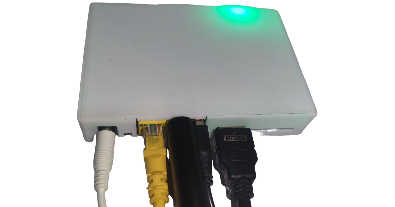
Plug the HDMI-to-USB capture card into the USB port near the Ethernet jack. Connect the HDMI cable from the capture card to the target machine. Plug the USB male-to-male cable into the USB port near the HDMI port, then connect Ethernet and power.
On the target machine, connect the HDMI cable and USB male-to-male cable to the corresponding ports.
Reminder
If you plug the OneCloud USB devices in reverse, PiKVM remote control features will not work.
Tip
Some low-power devices may draw power from OneCloud via the USB male-to-male cable when their main power is off, causing an abnormal state and preventing boot even after power is restored. To fix this, peel the cable and cut the red 5V wire.
Tip
Default web and VNC credentials are admin/admin and are synced. The root password is usually set by the user; if unset, try 1234.
SSH default port: 22
Web ports: 80, 443
VNC port: 5900
Janus WS port (disabled by default): 5009
Tip
Troubleshooting guide:
Web video shows "No Signal": check hardware connections.
Web page shows a black screen or colored vertical bars: check HDMI input from the target machine.
OS display is normal but BIOS is black or renders incorrectly: try enabling CSM in BIOS.
Mouse offset or abnormal movement: switch to relative mouse mode in the top-right of the web UI.
Screen goes black briefly and repeats after refresh: try Firefox.
If none of the above apply, reboot OneCloud to reset. If still not resolved, open a GitHub issue or join the One-KVM group.
MSD
Mass Storage Drive (MSD) enables remote file upload and image mounting. Due to Linux limits, CD-ROM format is capped at 2.2 GB, while FLASH format is unlimited.
Warning
Do not unmount images when the USB male-to-male cable (OTG) is disconnected or the target machine is powered off. Otherwise, the kernel may spam errors, the logging service can hit 100% CPU, and the system becomes unstable. MSD will remain unavailable until OTG is restored.
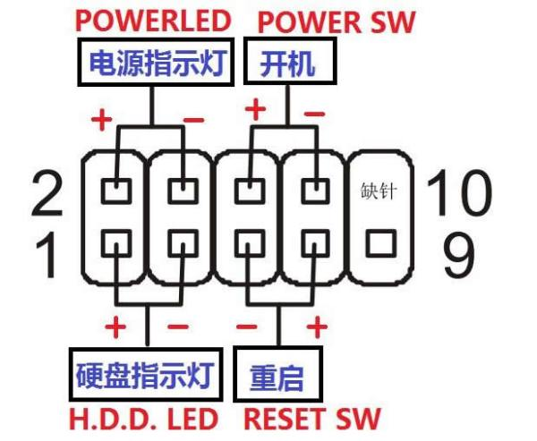
ATX Power Control
To use ATX power control, connect the power switch cable (for current dark kit cables, the dark lead goes to the negative pin and the light lead goes to the positive pin; for example, black/white and brown/red, orange/yellow map to negative/positive). Extension cables are not color-coded.